
Load paths and wall bracing in Minnesota framing
Published October 28, 2026
Reviewed October 28, 2026
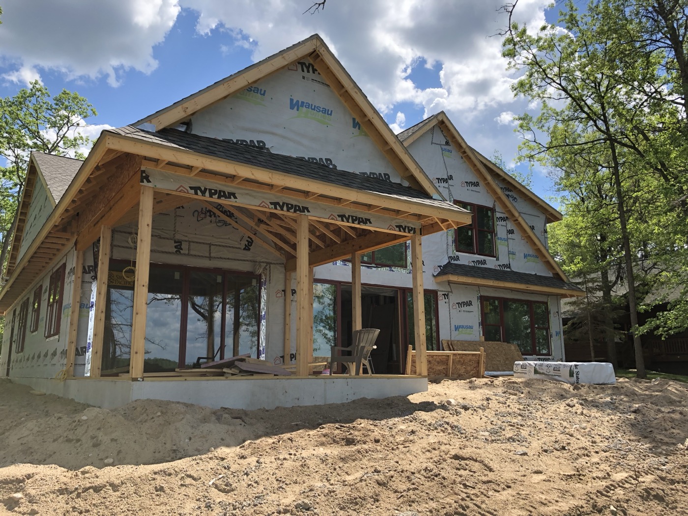
An open kitchen, a wide garage door, and a wall of windows can make a house work beautifully for the people living in it. They also change how the structure carries loads. The important framing decisions are often hidden around the edges of those openings and in the floor or foundation below.
A load path is the connected route a force takes through the building to the supporting ground. Understanding that route helps a homeowner ask better questions without trying to size a beam or design a shear wall.
Follow the weight all the way down
Start at a roof or floor and trace what supports it. A beam may deliver concentrated loads to posts. Those posts need adequate support below, which might include blocking, another beam, a foundation wall, or a footing designed for that load.
The 2020 Minnesota Residential Code’s R301.1 establishes the overall structural design framework. DLI describes the need for a complete load path transferring imposed loads through the foundation to the supporting soil. Sections R502.6 and R602.7 address important bearing and header requirements within that framework.
For a practical plan review, pick one major beam and ask the builder or designer to trace its support. A large member is not a complete solution if its end support or the structure beneath it has not been resolved.
Wind introduces a different direction of force
Weight acts downward. Wind can push against walls and pull upward on a roof. The roof, walls, floors, and foundation need the connections and bracing appropriate to those forces.
That is why a tidy row of studs is not the whole lateral-resisting system. Sheathing, fastening, blocking, braced wall panels, anchors, and required hold-downs may work together. Their arrangement matters as much as their presence somewhere on the site.
Minnesota Rules 1309.0301 sets amended climatic and geographic structural criteria. Wind exposure is evaluated for the site, while ground-snow-load information comes from part 1303.1700. Residential energy climate zones 6 and 7 do not replace either structural determination.
Treat wall bracing as a planned system
Section R602.10 addresses wall bracing. R602.12 offers a simplified alternative only where its eligibility conditions are satisfied. Where a building or portion does not fit the applicable prescriptive provisions, the design needs the appropriate engineered solution.
DLI’s residential inspection training identifies the bracing plan, sheathing and nails, hold-downs, straps, and end conditions as review points. This is a useful reminder that “we sheathed the wall” is not a complete explanation of the bracing design.
Before framing, identify the required panels and connection details on the plans. Keep those locations clear of unreviewed openings, recesses, or service penetrations. If a panel must change, review the whole affected detail rather than just replacing the missing sheet material.
Large openings need more than a bigger header
A wider door or window can affect both gravity support and the wall length available for bracing. A change that works for the header may still create a lateral-design problem beside the opening.
A garage door is a familiar example. The remaining wall segments may be narrow, and the approved design may call for a particular portal-frame detail or engineered system. The header, posts, anchors, straps, and sheathing installation then need to match that system.
Make major opening decisions before the foundation and framing details are finalized. If a homeowner requests a late change, ask the designer to identify every affected element and provide the revised detail before work continues in that area.
Pay attention where systems meet
The roof-to-wall junction, floor rim, and sill-to-foundation connection are handoff points for structural forces. They are also places where air sealing, insulation, and weather protection must fit around the structural work.
Raised-heel trusses add room for insulation but require coordinated roof-to-wall details. Floor openings can interrupt ordinary framing layouts. Tall walls may fall under specific Minnesota stud-table conditions or require design beyond those tables. Each transition deserves the correct detail, not an assumption that the next trade will solve it.
Our raised-heel truss guide and fastener guide explain two common connection issues in more detail.
Recheck after other trades have worked
A framing handoff should happen before structural details disappear behind insulation and finishes. Compare the installed work with the final plans after plumbing, electrical, and mechanical rough-in have introduced their penetrations.
A useful handoff record includes the current plan set, truss information, approved engineered repairs, connector substitutions, inspection results, and a closed correction list. Photograph important concealed details with enough context to identify their location. A close-up of a strap is more useful when another image shows which wall it belongs to.
This record does not replace inspection. It helps the owner and project team understand what was installed and makes later questions easier to resolve.
Plan the connections while choices are still open
The most productive time to discuss a load path is before a desired opening becomes an expensive field change. Bring the framing contractor into the coordination conversation with the building designer and the other relevant trades.
Contact Timberline Framing with your project plans, location, and proposed schedule. If you are still comparing options, start with our cold-climate roof guide and framing inspection checklist. Together, they give you a practical way to discuss the frame before it is covered.